
Respectfully to all those affected by Cyclone Gabrielle and other recent extreme weather events, a review of the options when installing a Mains – Off – Gen switch, and the prescribed electrical connection of standby generators, may be timely and relevant.
Today, it is not only plant such as chillers and freezers that require auxiliary power during a mains failure, as everyday operations across farms, orchards, vineyards, small business and homes rely on electricity for basic communication and operational functions – for example home based medical equipment.Computers are everywhere and the facility to connect a stand-by generator has become a frequent requirement for many businesses and homeowners.
The prescribed connection of both permanent and temporary generators is covered by the electrical standard AS/NZS 3010 which should be referenced in all instances. The following information is taken from the standard, however is not a complete and full summary and does not replace the standard.
Function
The purpose of a Mains Off Generator switch is to safely enable a load to be supplied by either Mains Power or Auxiliary Power – and ensure only one source can be connected to the load at any time. An Off position to isolate the load from either power source is a very popular option, for maintenance of the load, for example.
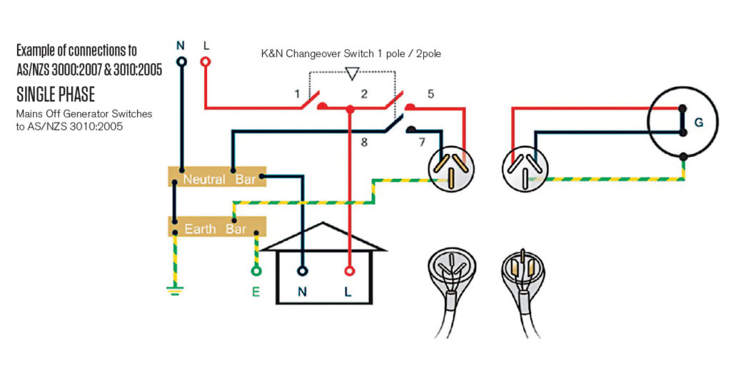
In reference to ‘standard’ Single Phase or Three Phase and Neutral installations, all phases are switched on both the Mains and Generator sides. However, as New Zealand installations employ a MEN (Multiple Earth Neutral) connection at the Main board, the Neutral on the Mains side must not be switched – it must be permanently connected.
Conversely – the Neutral from the Generator supply is always switched, unless it is also permanently connected to the Neutral bar at the Main board. There are exceptions with some installations and AS/NZS 3010:2005 should be referenced for all details.
Very Importantly – in Three Phase applications, the switch must be designed such that when switching to the Generator supply, the Neutral from the Generator supply is connected (contact closed) before the Phases from the generator are connected (contacts closed); inversely when switching back to OFF from Gen, the Neutral contact opens only after all Phases are disconnected (contacts open).
In Single Phase applications, the Neutral contact shall open and close simultaneously with the Phase contact.
Connection Diagrams according to AS/NZS 3010:2005
Please refer to the following diagrams for Single Phase and Three Phase installations.

Frequently Asked Questions
Here are a list of FAQ’s that are often raised by installers (answers in accordance with AS/NZS 3010:2005)
Q. Can I replace a permanently connected main switch with a MOG switch?
A. A permanently connected changeover device (MOG switch) with an intermediate OFF position may replace a main switch.
Q. Do I need to switch the Generator Neutral on permanently wired Generators?
A. When a Generator Neutral is permanently wired to the Main Neutral bar and a MEN link is provided, there is no requirement to switch the Generator Neutral. The Main supply Neutral is not switched.
Q. Do I need to switch the Generator Neutral on removable Generators, i.e., connected with an appliance inlet?
A. When a Generator is not permanently wired there is a requirement to switch the Generator Neutral. The Main supply Neutral is not switched.
Q. Do I need to switch Neutrals where there is no MEN link?
A. The Generator Neutral is switched. The Mains supply Neutral is not switched.
Q. Why do I need an Early Make Late Break Neutral?
A. The Neutral must not close after the main contacts, or open before the main contacts. In practical terms, a late make early break contact development is required.
Q. Is it possible to have a Multi-source changeover switch?
A. Switches are available for multi-source installations. e.g., mains, generator, solar, turbine.
Q. Can it be mounted in modern domestic distribution boards?
A. Switches are available with MCB fronts and shallow handles which fit inside modern distribution boards
Selecting a Mains Off Gen Switch
The following information is required when selecting a Mains Off Gen Switch
- Supply current (Amps)
- Mains cable size
- Switched neutral on the generator yes / no (see FAQ’s above)
- Mounting Data (panel mount, base mount with long shaft and door clutch, DIN mount with MCB front plate)
- Enclosed indoor / outdoor
- With an appliance inlet plug (if yes what amperage)
The Range and Options for Mains Off Gen Switches
The following are examples of popular Single and Three Phase MOG switches and mounting options although there are many more variations and custom options available.
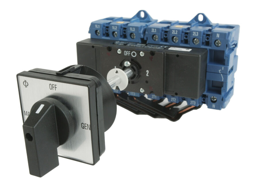
KN416
63A 1Ø Mains-Off-Gen
1 Pole + Thru Neutral Mains / 2 Pole Gen Din Mount – 4 MCB Spaces
KN417
63A 3Ø Mains-Off-Gen
3 Pole Mains / 4 Pole Gen
Din Mount – 7 MCB Spaces
MOG631-32P
63A 1Ø Mains-Off-Gen
1Pole + Thru Neutral Mains /
2 Pole Gen Enclosure IP65 Outdoor
Use: 280x190x180
32A 3 Pin Appliance Inlet
MOG633P
63A 3Ø Mains-Off-Gen
3 Pole Mains / 4 Pole Gen
Enclosure IP65 Outdoor Use: 280x190x180
63A 5 Pin Appliance Inlet
MOG1253P
125A 3Ø Mains-Off-Gen
3 Pole Mains / 4 Pole Gen
Enclosure IP65 Outdoor Use: 380x280x180
125A 5 Pin Appliance Inlet
KN408
80A 3Ø Mains-Off-Gen
3 Pole Mains / 4 Pole Gen
Base Mount – Door Clutch
In Summary
Please refer to pages 28 – 33 of Kraus & Naimer’s local catalogue to view more of the range or contact your local Powerbase Branch for further information; Catalogue: https://flippingbook.krausnaimer.com/Catalogue_NZL/29/
![]()